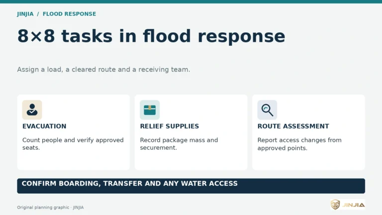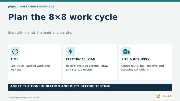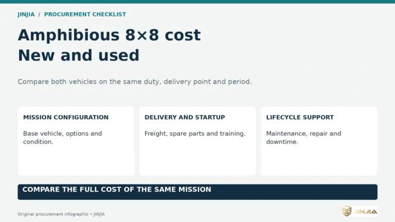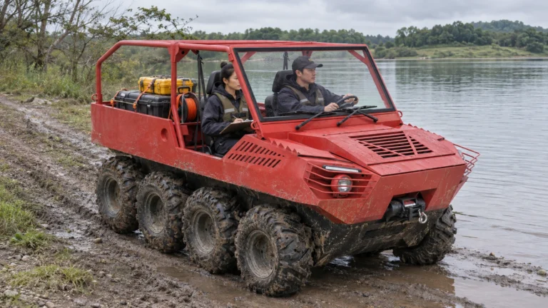


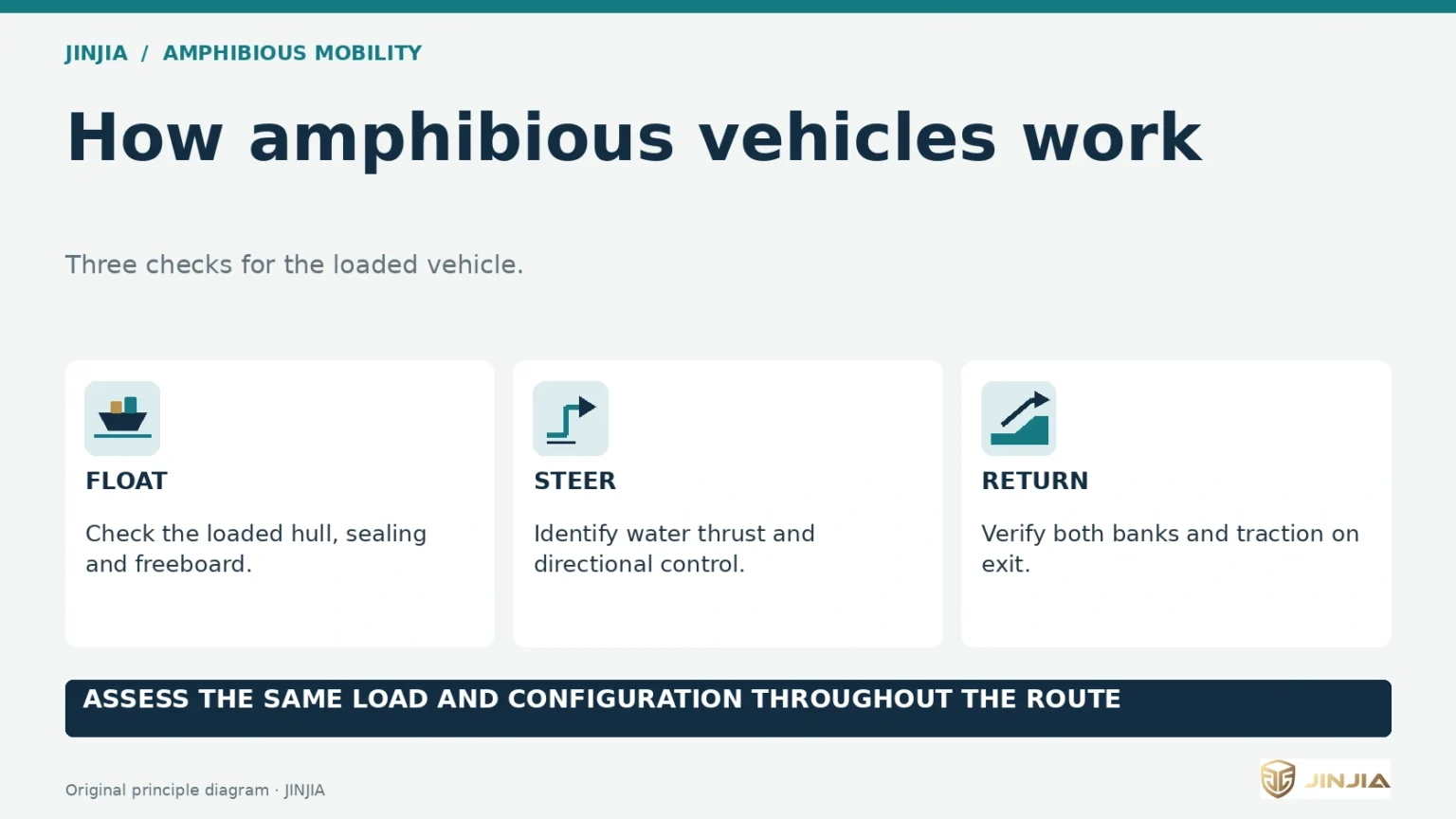
Buoyancy supports the loaded hull, propulsion controls travel afloat, and the exit depends on regaining traction.
What changes between land and water
How do amphibious vehicles work when the wheels or tracks lose contact with the ground? On land, the running gear supports the vehicle and delivers traction. In shallow wading, it can still bear part of the load against the bottom. Once afloat, water supports the loaded hull and the vehicle needs a means of producing thrust and controlling its direction. At the far bank, it must regain usable ground contact. Entry, afloat travel and exit each pose a different procurement question.
An 8×8 designation describes the wheel and drive arrangement. The hull, water propulsion, load distribution and suitable access points determine whether a particular 8×8 can complete a water crossing. The same principles apply to other amphibious vehicles, including tracked designs and purpose-built passenger carriers.
What the 88E and 88D evidence shows
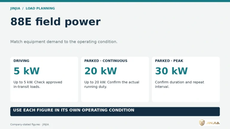
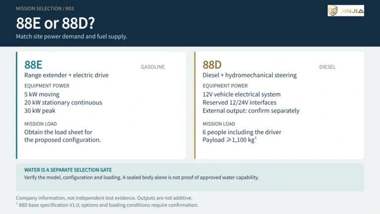
JINJIA describes its gasoline range-extended electric 88E as using two traction motors and a separate motor for water propulsion. This is one example of a dedicated water drive on a light 8×8. The configuration statement identifies the architecture. To assess a duty, ask for loaded freeboard, handling and transition records for the supplied build.
The 88D diesel technical specification documents a sealed, boat-shaped lower body. Its published specifications leave afloat payload, freeboard, stability and water speed to be confirmed. Treat this as a different evidence set. A specification sheet identifies design features, a labelled demonstration shows what was visible in that run, and a documented acceptance test pairs observations with a known configuration, load and set of conditions.
Buoyancy, sealing and stability under load
The hull displaces water. At rest afloat, the weight of the displaced water balances the weight of the vehicle, occupants and equipment. A heavier configuration generally sits deeper. Where the weight sits also matters. A high-mounted module can raise the centre of gravity. A load concentrated to one side or at one end can reduce the clearance between the water and a vulnerable opening in that area.
Freeboard is the vertical distance from the waterline to a specified point on the vehicle. Ask where it is measured and for measurements at the agreed loading. Sealing limits water ingress through the hull, joints, closures and penetrations. Useful evidence identifies which seals and closures were inspected, what the crew layout and equipment positions were, and how the vehicle behaved as weight was redistributed within its approved arrangement.
For example, take an inspection crew carrying instruments and cases. A demonstration with an empty deck says little about how that deck will sit once the crew and cases are carried. Include the load locations and restraints on the proposed layout, particularly where an upper module or rear cargo changes the balance.
Water propulsion depends on the design
Some amphibious vehicles use tyre tread shaped to push water as the wheels rotate. The ARGO Aurora 800 8×8 manual describes tyre propulsion and requires an outboard motor for water operation when the optional tracks are fitted. Verify the equipment and water limits for each configuration.
A propeller moves water to develop thrust. The vehicle’s steering response depends on the propulsion and control arrangement installed. A waterjet draws water through an intake and discharges it through a nozzle. A steerable jet can change thrust direction. These mechanisms place different demands on clearance, intake conditions and control at low speed.
The 88E illustrates separate drive functions. Its land traction motors drive the running gear, and a dedicated water propulsion motor serves the afloat duty. For any design, ask for evidence of how the supplied vehicle holds a course, turns and responds when thrust changes with its intended load. Record the tested wheels or tracks, propulsion hardware and operating conditions so the comparison can be repeated.
Entry and exit belong in the same acceptance test
Assess both banks in the directions the mission requires. The approach, near-shore depth profile, bed support, bank slope, surface grip and submerged obstacles can differ between entry and exit. During entry, the share of weight carried by the ground changes as the hull takes load. During exit, the vehicle must recover enough traction to leave the water with its cargo and crew.
Specify the actual departure and return points, intended load arrangement and permitted water conditions in the test plan. Agree how the team will document initial hull condition, control afloat and recovery of traction on exit. A successful launch from a prepared ramp demonstrates that specific entry. The return on a different bank needs its own observation and an agreed alternative if the route changes.
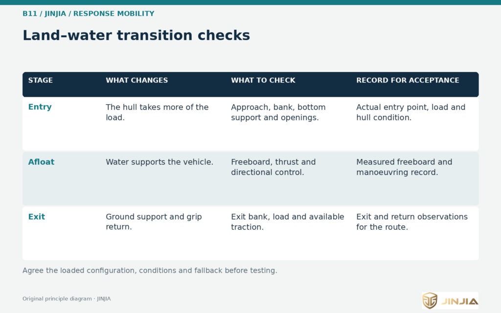
Review both banks and the conditions afloat with the same vehicle load and configuration.
When the route calls for a different vehicle
Use the manufacturer’s operating limits for the specific vehicle, with the site assessment and local requirements. A land payload rating, a shallow wading result and an afloat test describe separate operating conditions. A river crossing, flooded road or exposed waterway needs evidence for that environment. The US National Weather Service advises motorists to avoid flooded roads. Public floodwater guidance does not establish a usable route for a specialist vehicle.
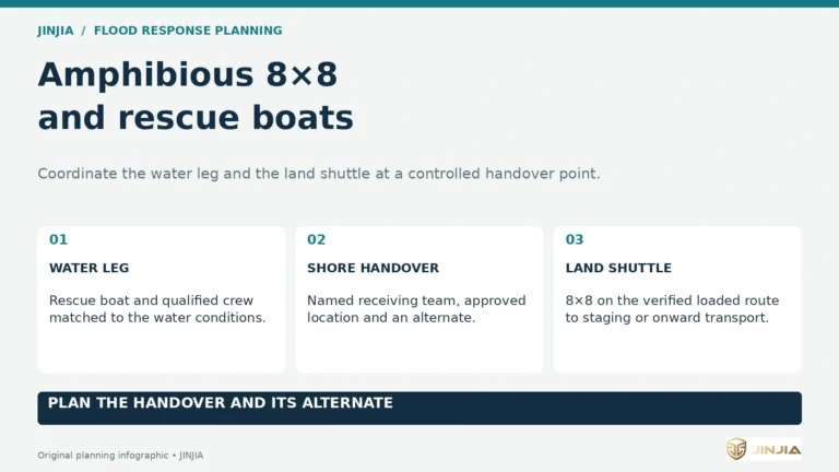
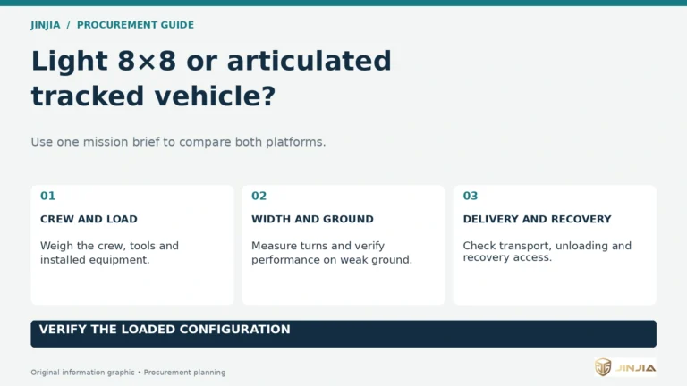
A rescue boat may suit a mission primarily conducted afloat, with transport or a crew staged at a suitable access point. A verified land approach may suit a job where the wheels or tracks can stay on a supported route. Evaluate these options on the same route, carried load, landing points and recovery arrangements before choosing a vehicle.
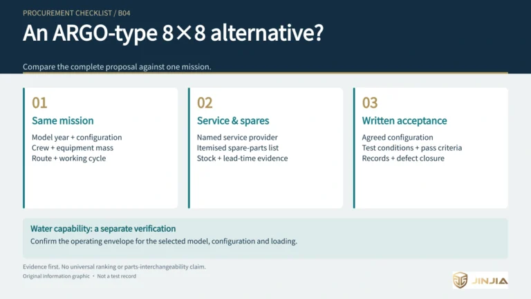
A one-page checklist for buyers
• Route. Mark entry, exit, return and fallback locations. Describe both bank surfaces, near-shore conditions and the intended travel direction.
• Mission load. Record people, PPE, equipment, consumables and recovery gear. Give each load’s location and the proposed wheels, tracks and upper equipment.
• Hull evidence. Request inspection records and loaded freeboard measurements at defined points, together with the approved balance and afloat load limits.
• Control and transition. Identify the fitted propulsion and controls. Agree how to document handling afloat and regaining traction at both required banks.
• Operating limits and recovery. Agree the allowed conditions, stop criteria, responsible team and alternative means of completing the mission.
For background, see what makes an 8×8 amphibious vehicle, the range-extended 8×8 architecture and the 8×8 versus rescue boat comparison. Send JINJIA your route, mission load and working conditions to discuss the configuration and the evidence needed for acceptance.
Frequently asked questions (FAQ)
A: Request the sealed-body inspection record, allowable afloat load, and freeboard at specified points for the intended configuration. Include people, fuel and equipment in the load description.
Q: How should water propulsion method be documented?
A: Identify the fitted wheels or tracks, the source of water thrust and the steering controls. Request a record of course-keeping and turning with the intended load and agreed water conditions.
Q: What evidence is needed for conditions at entry and exit?
A: Record each bank and travel direction, the load arrangement and conditions at the water’s edge. Ask how the configured vehicle was shown to enter, manoeuvre afloat and regain traction on exit.
Sources and further information
[S92] JINJIA 88E propulsion architecture · company source
[S91] JINJIA 88D Diesel 8×8 Technical Specification V1.0 · company source
[S89] JINJIA amphibious utility vehicle overview
[B11-E1] U.S. Coast Guard · A Best Practices Guide to Vessel Stability
[B11-E2] ARGO · Aurora 800 8×8 Operator’s Manual (2025)