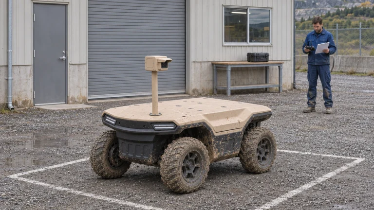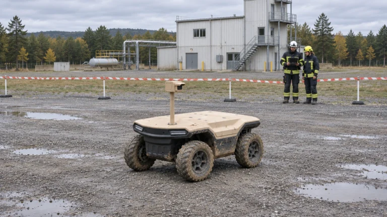


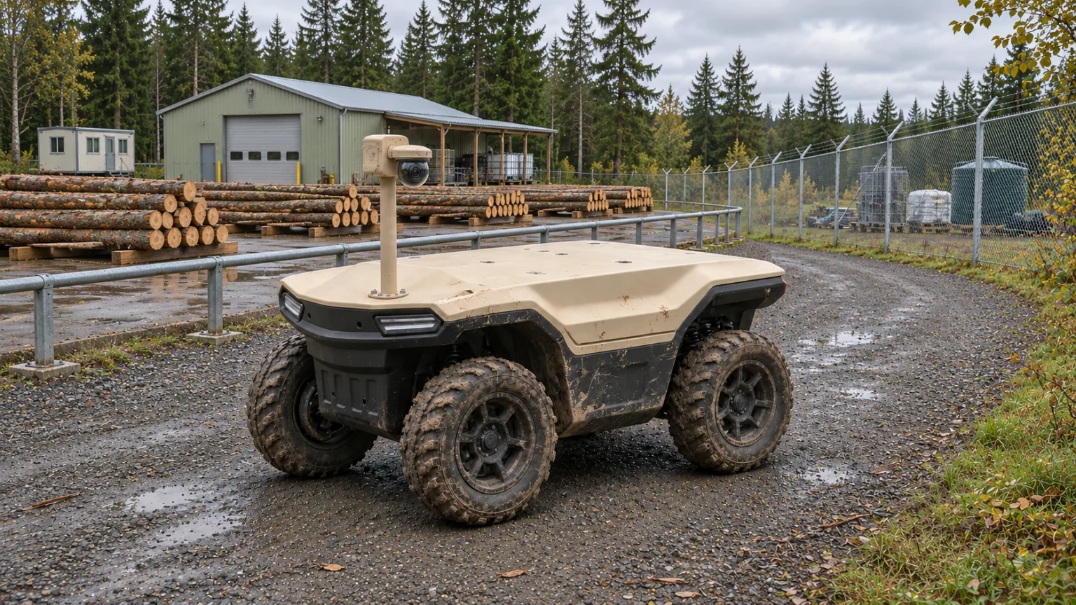
Yes: cameras, brackets, protective enclosures and their installed cables all belong in the payload budget. Inspection UGV payload planning should count the complete task installation, then check its position, electrical demand and effect on the route. A camera’s catalogue mass alone cannot establish that the installation fits.
JINJIA positions Delta 150 as a compact 4×4 UGV in the 150 kg payload class. Confirm the allowable installed load for the proposed vehicle and operating conditions in the technical proposal. This series uses AGV for Autonomous Ground Vehicle; industrial usage may also mean Automated Guided Vehicle. Neither term replaces a payload calculation or installation review.
At a glance
• Count the entire installed task kit against a defined vehicle baseline.
• Review mass, mounting geometry, views and electrical demand separately.
• Weigh and test the final assembly; a spreadsheet total is an input to approval.
Contents
Define the vehicle baseline and what counts as payload
Include equipment, brackets and protective enclosures
Check mass distribution and the required views
Define electrical connections and power demand
Freeze an assembly list that can be checked
Verify the complete installed payload on the route
Frequently asked questions (FAQ)
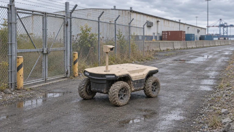
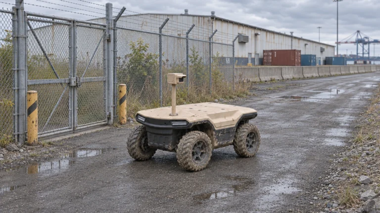
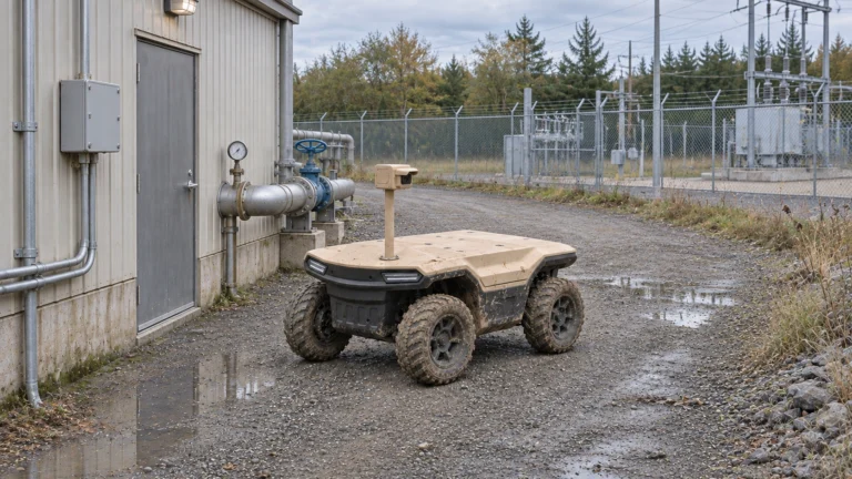
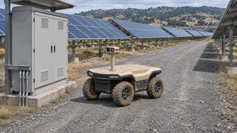
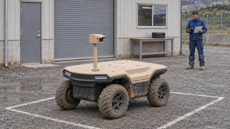
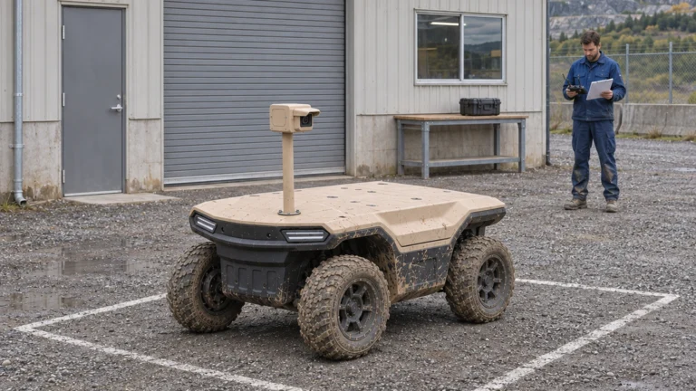
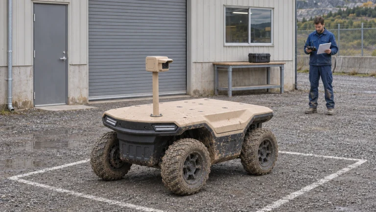
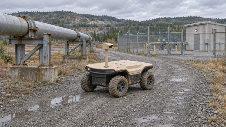
AI concept: proposed task-equipped Delta 150; configuration subject to confirmation.
Define the vehicle baseline and what counts as payload
Start with a configuration record for the supplied vehicle. Identify its battery, standard equipment and any hardware already included in the baseline mass. Then list every task addition. This prevents both omitting a heavy enclosure and counting a built-in component twice. Record whether each mass is measured, quoted or still unknown.
Payload and total vehicle mass are different quantities. Use an agreed baseline when comparing the assembled vehicle with the unloaded configuration. The 150 kg class does not mean that every 150 kg shape or placement is acceptable. Obtain installation-specific restrictions for the mount, load distribution and route before treating the class value as a working allowance.
Include equipment, brackets and protective enclosures
Build the list from the complete assembly rather than the sensor quotation. Include mast, base plate, fasteners, camera, enclosure, router, computer, antenna, cables, converters and any added battery. Count carried tools or cargo as well. For a removable module, identify which parts stay on the vehicle when the module is removed.
Add quantities and units, then calculate quantity multiplied by unit mass for every line. For illustration only, an 8 kg camera, 6 kg mast, 4 kg enclosure and 2 kg cable kit total 20 kg before other additions. Those are arithmetic inputs, not Delta equipment weights or an approved configuration. Keep unknown items open instead of entering an invented zero.
Check mass distribution and the required views
Place each component on a drawing with a consistent vehicle coordinate reference. A tall mast and a low box can have the same mass but produce different assembled layouts. Review overhang, attachment loads, access, wheel clearance and the camera view with the integrator. Also check whether equipment blocks navigation sensors, service access or the means of stopping the machine.
Clearpath’s mobile-robot manual provides a useful external example: attachments count toward payload and the combined robot-and-payload mass distribution needs assessment. Its stability limits belong to that product. For Delta, use the actual assembly and approved engineering limits. Do not calculate an allowable side slope from a publicity photograph or infer stability from remaining kilograms alone.
Define electrical connections and power demand
For each powered item, request its input voltage, average operating demand, startup or peak demand, connector and control interface. Separate vehicle supply limits from a sensor’s own rating. Confirm available continuous and transient power at the intended connection. Extra battery mass, converter losses and enclosure heat also belong in the integration discussion.
Calculate a preliminary sum for the intended operating state, then have the integrator check which loads can run together. The supplied workbook totals entered device demand; it does not prove power-rail compatibility. Inspect cable routing through moving joints, protection at entries and clearance during steering. Mechanical mounting, electrical supply and software integration need separate sign-off.
Freeze an assembly list that can be checked
Give the proposed kit a revision and list component identifiers, quantities, unit masses, power figures and mounting locations. Attach the drawing, interface descriptions and source documents. Mark estimates clearly. Link each unresolved item to an owner and next action so the team can see whether the design is ready for weighing or still awaiting a supplier answer.
Use a matching list for procurement and assembly. For example, replacing a bracket with a taller version is a configuration change even when the camera model remains unchanged. Update the mass and view records before testing. Do the same after adding a modem, protective guard or larger battery; small changes accumulate across the installation.
Verify the complete installed payload on the route
Weigh the final kit and compare it with the approved baseline and bill of materials. Record the measuring method and uncertainty appropriate to the decision. Check fasteners, cable protection, access, sensor views and the integration documents before a controlled route trial. Test the intended load arrangement rather than an unloaded vehicle and a separate sensor demonstration.
Record the trial’s surface, speed, slopes, stops and operating state together with observations and exceptions. A passing mass sum does not establish stopping behaviour, stability, camera performance or shift endurance. Delta 500 and Delta 1000 require separate payload designs. Send JINJIA the installation list and route to discuss whether Delta 150 UGV/AGV fits the task or another platform should be assessed.
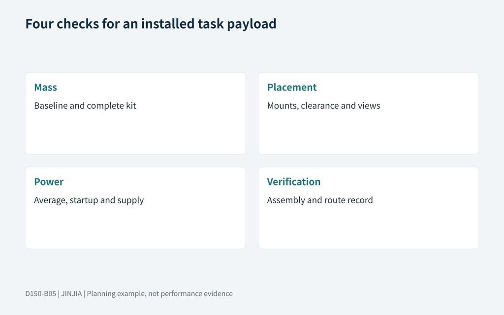
JINJIA planning framework; example inputs are not test results.
| Review | Evidence to collect |
| Mass | Baseline and complete kit |
| Placement | Mounts, clearance and views |
| Power | Average, startup and supply |
| Verification | Assembly and route record |
Send the complete equipment list and route to discuss Delta 150 UGV/AGV payload integration.
Frequently asked questions (FAQ)
A: Yes. Count the complete installed task kit, including mounts, protection, cables and any added power equipment.
Q: Is payload the same as total vehicle mass?
A: No. Establish which vehicle configuration forms the baseline, then identify the added task installation without omissions or double counting.
Q: Does 20 kg in an example describe a Delta camera kit?
A: No. It is a labelled arithmetic example; actual component masses must come from the selected assembly.
Q: Does mass below the limit prove the kit is acceptable?
A: No. Check mounting, mass distribution, sensor views, power, stopping behaviour and the proposed operating conditions.
Q: Can unused payload capacity power extra equipment?
A: No. Kilograms and electrical capacity are different constraints; confirm each power connection and operating state.
Q: When should the calculation be repeated?
A: After any relevant equipment, bracket, enclosure, battery or mounting change, and before accepting the final installed configuration.
Sources and further reading
Delta 150 payload class and task-scoping context; the selected configuration needs its own approved limits.
Clearpath — Husky A300 payload and stability guidance
Third-party integration reference on counting attachments and assessing combined mass distribution; its values and hardware do not apply to Delta.
Clearpath — Husky A300 integration guide
Reference showing separate mechanical, electrical and software integration work; no Delta connector or current limit is inferred.