

RTK equipment does not prove that every metre of a route supports the intended task. A UGV GNSS communications survey should check localisation, command delivery and the inspection stream separately. Then combine the results to decide which segments and operating modes the site can approve.
For Delta 150, begin with the proposed camera, antenna positions, power supply and working schedule. This series uses AGV for Autonomous Ground Vehicle; industrial usage can also mean Automated Guided Vehicle. Neither label establishes coverage. This guide describes a survey method, not a measured Delta coverage map or a guarantee of autonomous operation.
At a glance
• Survey the whole task route, including stops and return legs.
• Separate position quality, control delivery and video age.
• Record failures and recovery instead of averaging them away.
Contents
Check localisation beneath canopy and beside obstructions
Survey mobile and satellite links with their power demand
Treat Starlink as an optional link with installation limits
Separate link loss, localisation loss and sensor failure
Log switching, delay and recovery
Complete a route coverage and recovery worksheet
Frequently asked questions (FAQ)
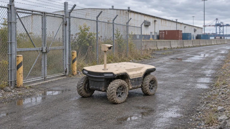
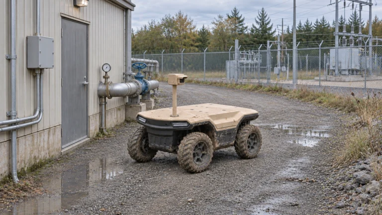
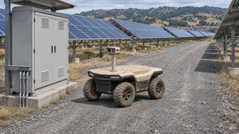
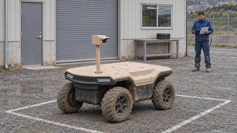
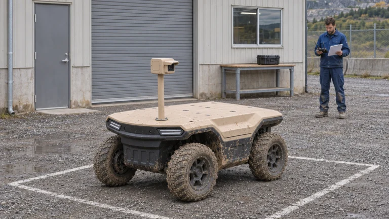
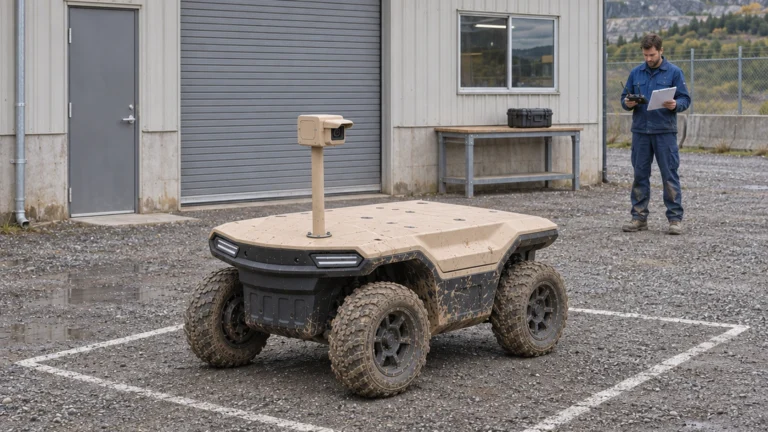
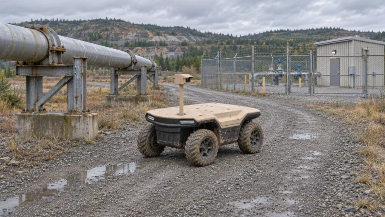
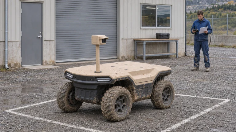
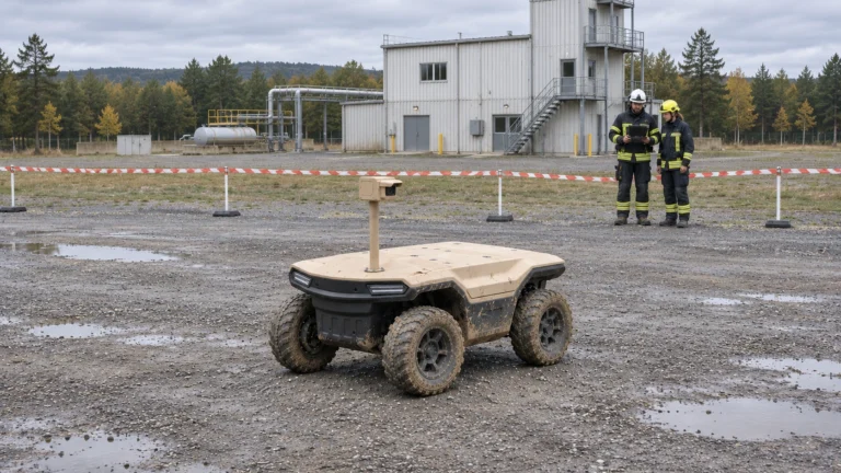
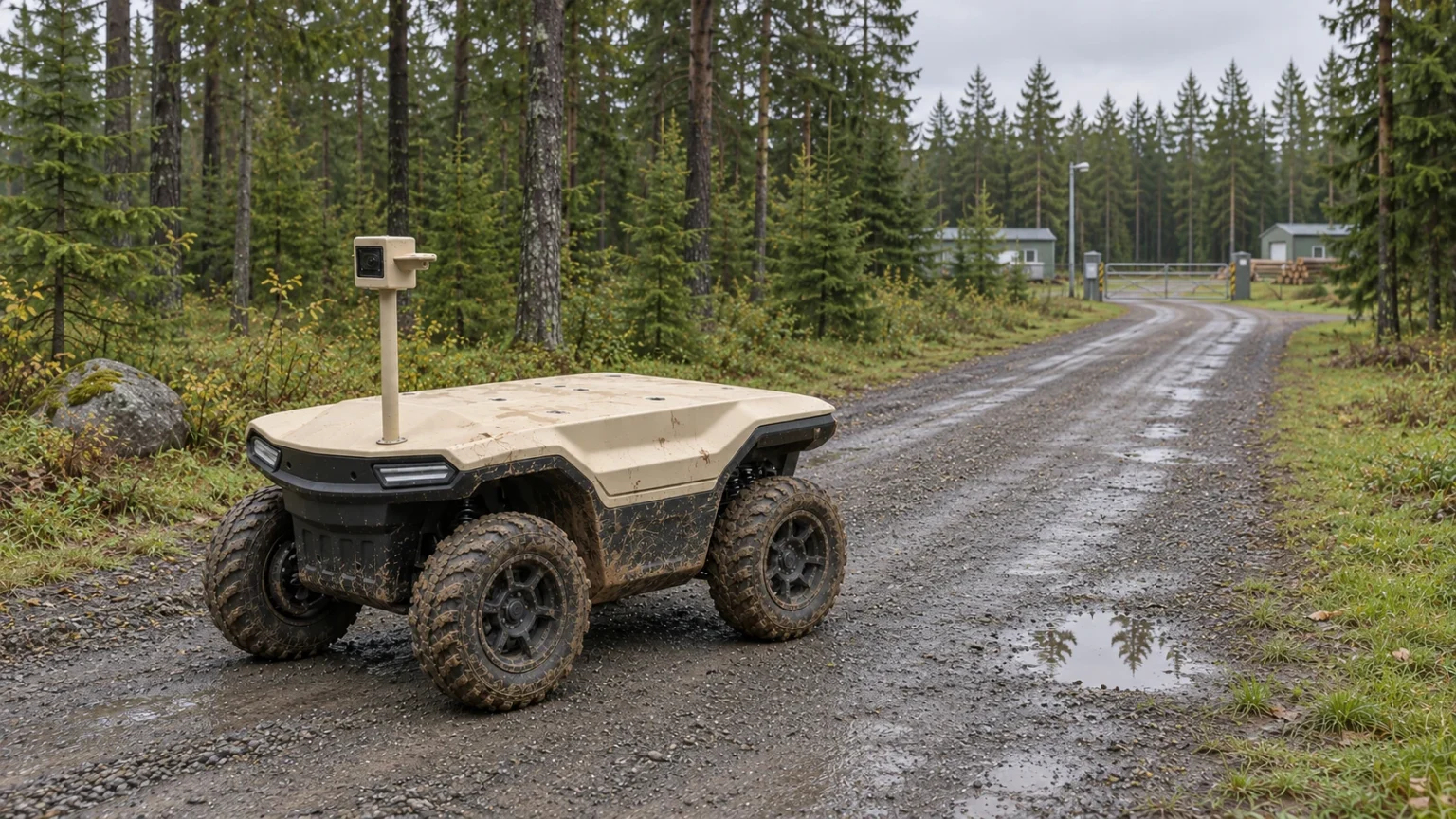
AI concept: proposed task-equipped Delta 150; configuration subject to confirmation.
Check localisation beneath canopy and beside obstructions
GPS.gov explains that receiver accuracy depends on local conditions as well as the satellite signal. Trees and structures can block signals, while reflections can produce multipath. Consequently, a receiver specification from open sky cannot establish performance beside a metal shed or beneath dense foliage. Treat the route environment as a test input.
Divide the route at changes in canopy, nearby structures, slope and required clearance. At each segment, record the localisation method, available quality indicators and an independently established reference where practicable. If the proposed system uses RTK corrections, include correction availability and age. Agree acceptable position error and loss behaviour with the integrator before a controlled trial.
Survey mobile and satellite links with their power demand
Check the actual mobile network and antennas at vehicle height, rather than treating a handset signal icon as acceptance evidence. Evaluate command acknowledgement, status delivery, video and file transfer under the proposed workload. A link may support a compressed image yet fail to support timely remote driving. Therefore, specify a separate requirement for each service.
Also measure terminal and router power in the intended installation. Include startup, data transfer and any standby period in the task energy budget. Record antenna clearance and cable protection when the robot crosses vegetation. A communications option changes both the network design and the equipment load; do not treat it as a software-only addition.
Treat Starlink as an optional link with installation limits
Starlink’s Standard 4 guide requires a clear sky view and identifies obstructions as a cause of service interruptions. That guidance supports checking the proposed mounting location. It does not establish that a particular terminal or service plan permits the intended moving-vehicle use. Confirm current hardware, plan, territory and installation requirements separately.
For example, a stationary relay at a clearing and a terminal carried beneath a forest canopy are different architectures. Trace every hop between operator and robot, including the local link from a relay. Test each hop and the complete path. Neither the satellite brand nor a successful test at the base station proves coverage along the inspection route.
Separate link loss, localisation loss and sensor failure
A command channel can fail while localisation remains usable. Conversely, the robot may still report status after position quality becomes unsuitable. A dirty task camera creates another failure: the vehicle can travel but cannot collect the required observation. Because these conditions differ, assign separate event codes, operating restrictions and recovery responsibilities.
Verify the delivered response for each event in a controlled area. Do not assume that automatic return remains possible after a navigation fault, or that a video reconnection restores command authority. Document what the operator sees, which commands remain available and what must be checked before restarting. Keep unresolved behaviour outside the approved operating scope.
Log switching, delay and recovery
If the design proposes multiple links, define how selection and switching work. A second subscription is not evidence of automatic failover. Test transitions with the intended video load, route task and control station. Record interrupted sessions, authentication changes, acknowledgement gaps and the time needed to restore the required service.
Use consistent timestamps for command issue, acknowledgement, image capture and reception. Clock alignment must be known before deriving a delay from different devices. Also record the active link, operating mode, route version and equipment configuration. Keep individual outages visible: a good average can conceal a long gap at the most important observation point.
Complete a route coverage and recovery worksheet
Create one record for each segment and observation stop. Include the proposed service, acceptance criterion, trial conditions, measured result, failure response and evidence owner. Repeat the survey after a relevant antenna, software, route or seasonal change. Unknown cells are follow-up actions, not successful results. The accompanying worksheet provides a starting structure.
Use the findings to approve a smaller route, change the communications layout or request another controlled test. Delta 500 and Delta 1000 require their own installation assessments. Send JINJIA the route, obstructions, payload, schedule and available networks to discuss a Delta 150 UGV/AGV configuration. No project coverage or unattended operation is promised by this planning guide.
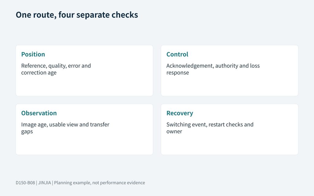
JINJIA planning framework; example inputs are not test results.
| Survey layer | Record by segment |
| Position | Reference, quality, error and correction age |
| Control | Acknowledgement, authority and loss response |
| Observation | Image age, usable view and transfer gaps |
| Recovery | Switching event, restart checks and owner |
Send the route, task equipment and network constraints to discuss Delta 150 UGV/AGV.
Frequently asked questions (FAQ)
A: No. Confirm correction delivery, receiver conditions, actual position performance and the response to inadequate localisation on each segment.
Q: Is a mobile coverage map sufficient?
A: No. Survey the actual terminal and services at the intended installation height and operating workload.
Q: Can Starlink solve dense canopy coverage by itself?
A: Do not assume so. Check sky view, terminal suitability, service conditions and every local network hop.
Q: Does two-link hardware prove automatic switching?
A: No. Confirm the implemented selection logic and test session interruption, command delivery and recovery.
Q: What should the test log retain?
A: Segment, conditions, configuration, service criteria, timestamps, individual faults, actual recovery and an evidence owner.
Q: When should the route be surveyed again?
A: After changes that may affect the task, such as antenna position, software, foliage, construction or a revised route.
Sources and further reading
General signal blockage and multipath principles; archived page, not a Delta route test.
Starlink — Standard 4 setup guide
Supports the clear-sky and obstruction discussion for this terminal; does not approve mobile use or Delta integration.
Model context; link hardware, software and supported modes require configuration confirmation.